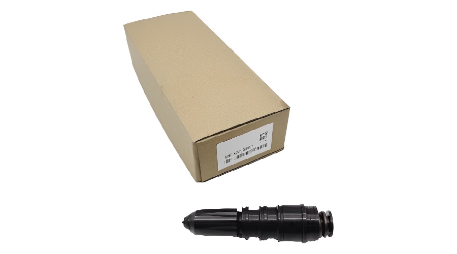
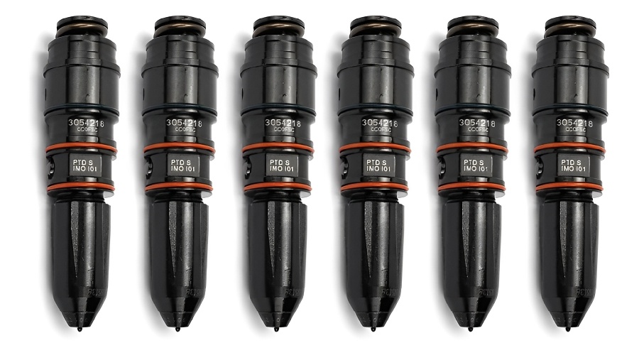
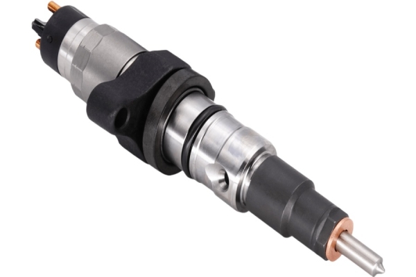
What kind of CUMMINS N855 fuel injector 3054218 will you get ?
1. You’ll get it all with; 100% O-ring replacement for proper sealing, a new Actuator Assembly, Spill Valve, To top it off, every nozzle is tested for 100% proper fuel delivery. It just doesn’t get much better than that.
2. Meticulous testing? You got it! This injector goes through a strict reassembling and testing process for fuel delivery, injection pressure, and timing. If you want more power and reduced emissions, this is the way to go.
3.To put things in perspective, you’re getting proper fit and function because strict OE specifications are met.
There’s no doubt you’ll get exceptional quality and consistency. Why? Each injector is completely disassembled, components are cleaned, and lastly this bad boy is checked for wear and breakage. It comes from the reconstruction of China's top fuel system OEM manufacturing factory, you can't beat it
Structural principle and disassembly steps of PT type fuel injector for Cummins N855 generator set
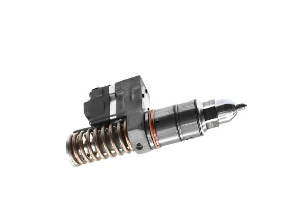
The structure of the PT injector in Cummins generator sets is significantly different from that of ordinary injectors, and its precision requirements are also higher. The PT injectors used in Cummins diesel engines must be disassembled, inspected, and debugged using specialized tools and equipment. Maintenance can be carried out by referring to the corresponding Cummins diesel engine maintenance manual. This article introduces the PT fuel injection classification of diesel generators and provides a detailed explanation of each one, along with its working principle and structural diagram.
1、 Cummins generator set PT injector classification
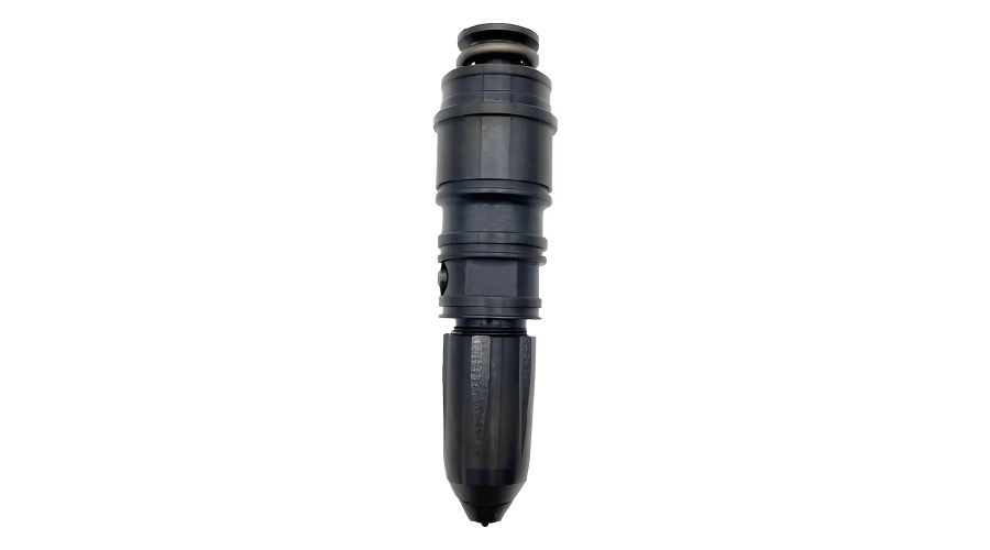
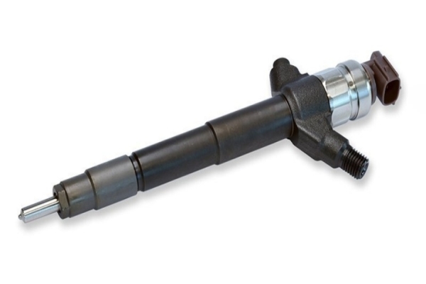
PT injectors are divided into two types: flange type and circular type. Flange type fuel injectors are installed on the cylinder head with flanges, and each injector is equipped with an inlet and outlet oil pipe; The inlet and pump oil safety channels of the cylindrical fuel injector are built on the cylinder head or cylinder body, and there is no flange installed. It is pressed on the cylinder head by installation wheels or pins, which not only reduces common faults caused by pipeline damage or leakage, but also simplifies the appearance design layout of diesel generators. The cylindrical fuel injector can be divided into PT type, PTB type, PTC type, PTD type, and PT econ type. The. pt econ type fuel injector is used on diesel generators with strict regulations on exhaust pipe environmental pollution.
2、 Structure and principle of PT injector for Cummins generator set
The principle of flange type and round steel pipe type fuel injectors is basically similar, but there are some differences in construction. Taking the flange type fuel injector on the Cummins nta855 diesel generator as an example, the structure and principle of the PT fuel injector are demonstrated.
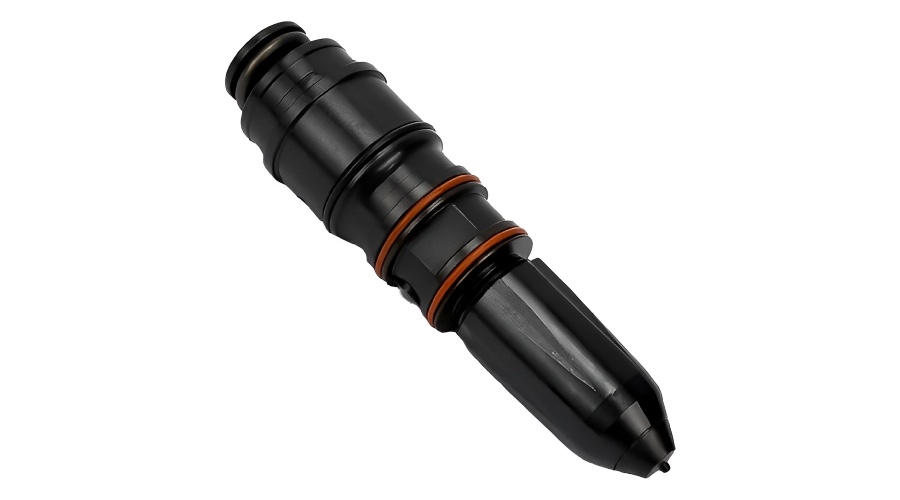
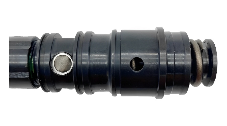
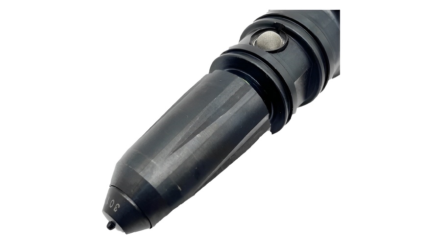
The structure of the flange type fuel injector is shown in the figure, which consists of the injector body, plunger, injector, spring, and spring seat Cheng. There are eight nozzles with a diameter of 0.20 millimeters below the fuel injector. The diameter of the cylindrical fuel injector for the n855 diesel generator is 0.1778 millimeters; The diameter of the cylindrical fuel injector for the NT-855 and nta-855 diesel generators is 0.2032 millimeters. On the fuel injector body of a diesel generator, there is usually a marking, such as 178-a8-7-17. The meanings of the marks in sequence are: 178- total flow of injector, a -80% total flow, 8- number of nozzles, 7- nozzle specification is 0.007in (0.1778mm), 17- injection angle is 17 spray angle. There are residual oil inlet holes, measuring and calibration holes, and residual oil return holes in the oil passage of the injector body.
The plunger is driven by the fuel injection camshaft (on the camshaft of the valve diesel generator) based on rollers, roller frames, swing rods, and crank arms. The fuel injection camshaft has a unique shape and rotates in the opposite direction (viewed from the timing gear end), with a speed ratio that is half of the crankshaft speed ratio of a diesel generator.
In the intake stroke arrangement, the roller flips and moves downwards on the camshaft sphere. When the crankshaft of the diesel generator rotates to the top dead center of the intake stroke arrangement, the needle valve plunger gradually rises under the elastic effect of the return spring, and the annular chamber space on the needle valve plunger communicates with the vertical main oil passage and the inlet passage. At this time, the measuring and calibration orifice is still closed. The diesel from the PT pump flows through the remaining oil hole, inlet passage, annular chamber space, vertical main oil passage, storage tank chamber, return remaining oil hole, and return main oil passage to the float car fuel tank. The return of diesel can provide cooling and lubrication for the PT injector.
When the crankshaft of the diesel generator rotates again to the top dead center of the intake stroke arrangement at 44 ° CA, the plunger rises to the position where the measuring hole for calibration is opened. After the calibration hole is opened, diesel gradually enters the conical chamber space below the plunger through the calibration hole.
When the crankshaft of the diesel generator rotates to 60 ° CA before the bottom dead center of the four stroke intake port, the plunger stops rising and then stays at the topmost part until 629 ° CA before the top dead center of the compression stroke. The roller gradually rises along the camshaft curve and the plunger gradually decreases. At 28 ° CA before the top dead center of the compression stroke, the measuring hole for calibration is closed. The opening time of the measuring hole and the oil working pressure provided by the PT pump determine the fuel injection quantity of each cycle system of the injector.
Then, the plunger slides down again and gradually sprays fuel when it reaches 22.5 ° ca before the top dead center is reduced. The diesel in the conical chamber space is sprayed into the combustion chamber of the diesel generator as mist under the high working pressure (about 98mpa) of the plunger's cut-off brake.
When the plunger slides down to 18 * ca after the top dead center of the reduced stroke arrangement, the fuel injection ends. At this point, the plunger exerts excessive pressure towards the conical bottom of the fuel injector, causing the diesel to be completely sprayed out. That way, it can avoid changes in fuel injection quantity and the accumulation of residual diesel carbides at the bottom of the injector. The working pressure of the plunger pressing towards the conical bottom can be adjusted with the adjustment screw on the crank arm, and the injector should be avoided from being crushed during adjustment. When the plunger slides to the minimum position, the camshaft is at the maximum position. Afterwards, the camshaft is recessed by 0.36mm, and the plunger maintains this position without changing until the work and exhaust pipe are terminated.
There is an adjusting washer between the roller frame cover and the car diesel generator body, which is used to adjust the timing of gradual fuel injection. If the gasket is thickened, the roller frame will shift and the timing of gradually spraying oil will be advanced. On the contrary, when the washer is lowered, the roller frame is offset, and the fuel injection lags behind.
The adjustment screw on the crank arm is used to adjust the working pressure of the PT injector plunger towards the conical bottom end. During the entire adjustment process, the torque method is used to adjust the torque of the screws to the required standard value using a torque wrench. When adjusting, make sure that the piston rod of the adjusted cylinder is located 90 ° ca after the top dead center is reduced.
3、 Disassembly and assembly steps and precautions for PT fuel injector of Cummins generator set
According to the reverse procedure of disassembly, the specialized clamping tool used for disassembly is still used for assembly. When assembling, the following points must be noted:
1. The mating surface of the installed parts must be clean, smooth, and even; Any defects must be repaired and qualified before assembly can proceed. Otherwise, it will result in incorrect fuel flow and affect the power performance of the diesel generator.
2. Only when repairing 5/16 type fuel injectors, a gasket needs to be placed between the sleeve and the injector body.
3. After installation, check whether the fuel injector and plunger are aligned; Remove the plunger and apply clean diesel or test oil; Then stand the fuel injector upright (with the nozzle facing downwards), hold the plunger, and let the plunger drop a few drops of test oil into the nozzle; Insert the plunger into the sleeve about 13mm away, and the plunger should be able to slide freely in; Press the coupling with your palm to seat the plunger inside the fuel injector, and move it 90 degrees. At this point, the compressed plunger must touch the surface of the fuel injector seat; When the fuel injector nozzle is quickly flipped upwards, the plunger should be able to slide out freely; If it cannot slide out, remove the plunger, loosen the plunger, loosen the tight cap, adjust the fuel injector (rotate 1/4 turn), tighten it 5 times, press it on for testing until it meets the requirements.
4. Check the nozzle holes: A simple method to check if the nozzle holes are unobstructed is to remove the plunger and spring, and inject clean fuel into the injector. Insert the plunger directly into the fuel injector without a spring; Quickly force diesel to flow out of the nozzle in order to check if the nozzle is in good condition.
5. PT (d) Injector Test
(1) Perform oil leakage test on the PTS301 injector test bench for fuel injection sequence. Mainly check whether there is oil leakage between the plunger and the sleeve, and between the plunger and the nozzle.
(2) Check the spray condition of the nozzle on the device pts301.
(3) Measure the fuel injection quantity on the fuel injector test bench.
① Check if there is any damage to the inner hole of the plunger sleeve. If the fuel injector passes the oil leakage test and the leakage does not exceed the limit, the sleeve can continue to be used. If there is too much oil leakage, the sleeve and plunger must be replaced together.
② Check the holes with a high-power magnifying glass to see if there is any change in the aperture of the two holes. If the measuring hole is damaged, the fuel injector will not work properly.
③ Check for any damage or unevenness in the shaded area of the image. Grind the flat surface, paint it blue, and check the flatness of the end face. If there are scars or unevenness, grind and repair them. During the cleaning process, do not use sandpaper or wire brush to clean the joint between the nozzle and the sleeve. First, dry the cleaned sleeve with compressed air and apply blue on the grinding plate to check the flatness of the end face. If any scratches or unevenness are found on the end face, it should be ground and repaired.
5. Check the steel ball and ball seat:
① Use a magnifying glass to inspect the steel ball for any scratches or rough marks. When the steel ball or ball seat is found to be damaged, the ball seat should be re ground and the steel ball should be replaced.
② The steel balls of this fuel injector are made of special materials and should not be replaced with regular steel balls.
6. Check the injector housing:
① Check for rough lines or other damages in the balance hole; Check if the two oil passages are connected.
② Check if the tight cap thread is damaged; Are there any scratches or rough marks on the installation area of the O-ring? Such damage will cause damage during the installation of the O-ring.
③ Check for scratches or rough marks on the mating surface with the sleeve. If any are found, they should be ground and repaired.