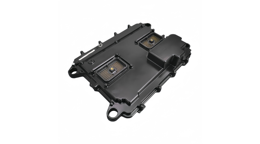
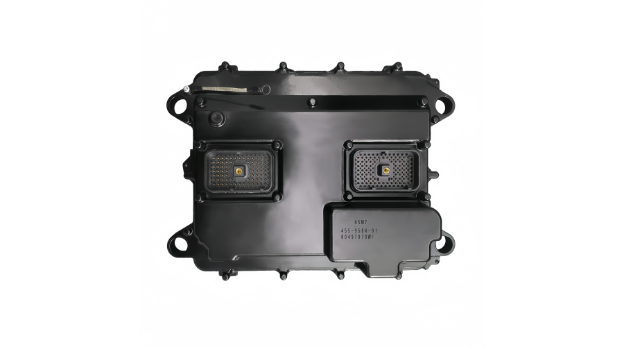
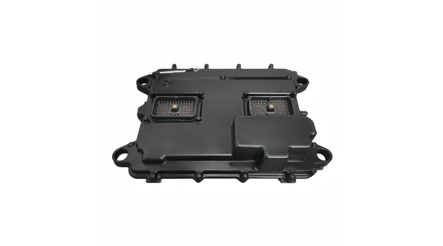
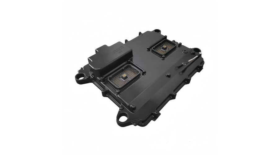
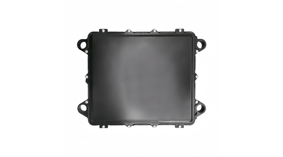
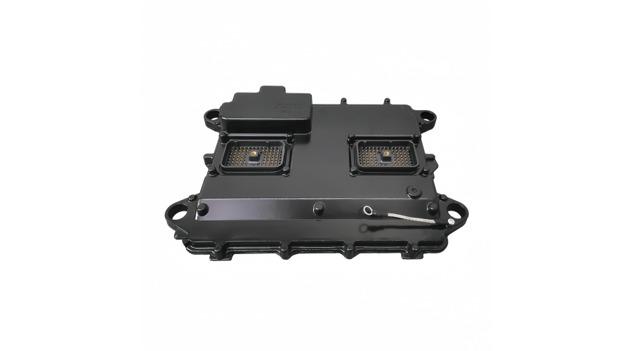
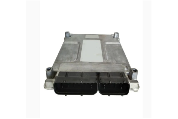
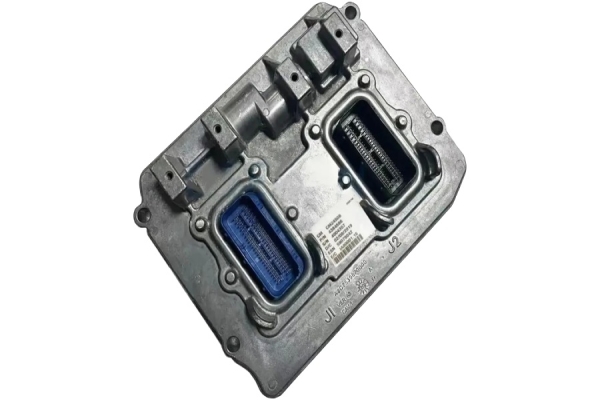
The part number 455-9584-01 is indeed a well-known and widely used Engine Control Module (ECM) for Caterpillar equipment.
Here are the key details and common applications for this ECM:
Primary Information:
Common Associated Engines & Equipment:
This ECM was used on a range of popular Caterpillar mid-sized engines, which powered countless machines. The most common engine models include:
C7 (7.2L)
C9 (9.3L)
C11 (11.1L)
C13 (12.5L)
These engines were installed in a vast array of equipment from the mid-2000s to early 2010s, such as:
Trucks: On-Highway Trucks (e.g., Kenworth, Peterbilt with Cat engines)
Construction Equipment: Wheel Loaders, Backhoe Loaders, Telehandlers, Paving Equipment
Industrial Equipment: Generator Sets, Pumps, Compressors
Material Handling: Forklifts, Reach Stackers
Important Notes for Service/Replacement:
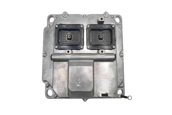
Software is Critical: This ECM is a "blank" computer. When replacing a 455-9584-01, it must be flashed with the correct software ("flash file") specific to the original engine's arrangement number and application. This software contains all the horsepower ratings, torque curves, and operational parameters.
Exchange Programs: Caterpillar and many independent remanufacturers offer exchange (core exchange) programs. You send in your faulty ECM (the "core"), and they send you a remanufactured one that is already tested and flashed to match your engine's specifications (if you provide the engine serial number).
Cross-References: You may also encounter related part numbers like:
455-9584 (the base number without the dash-01 suffix).
455-9584-02, -03, etc. (later revisions).
Other labels: It may also be found under an internal OEM number like 207-4579.
If You Need to Replace or Service This ECM:
Always have your Engine Serial Number (ESN) ready. This is the most crucial piece of information for technicians and parts suppliers to ensure you get the correct part with the correct software, ensuring your equipment runs properly.
In summary, 455-9584-01 is a core component for controlling many of Caterpillar's most successful engines, making it one of the most common ECMs in the field for that generation of equipment.How to perform high-quality reconstruction of old ECM?Performing a high-quality reconstruction (remanufacturing) of an old ECM is a sophisticated process that goes far beyond simple repair. It requires specialized equipment, deep technical knowledge, and strict procedures. Here is a detailed breakdown of the process performed by professional remanufacturers.
Core Philosophy:
High-quality reconstruction aims to restore the ECM to Original Equipment Manufacturer (OEM) performance and reliability specifications, not just to get it working temporarily. It focuses on root-cause failure analysis and systemic refurbishment.
Step-by-Step Process for High-Quality ECM Reconstruction
Phase 1: Intake & Diagnostic Analysis
Receiving & Tagging: The core ECM is tagged with a unique tracking number linked to the customer and engine serial number (ESN).
Visual Inspection: A thorough examination for:
Physical damage (cracks, burns, bent pins).
Corrosion or water intrusion (white/green deposits).
Previous tampering or poor repair attempts.
Bench Test & Full Diagnostic Scan:
The ECM is powered on a proprietary test bench.
All internal power supplies (5V, 12V, etc.) are checked for proper voltage and stability.
Communication networks (J1939 CAN, J1708, proprietary) are tested.
The stored fault codes, tattletales, and engine hours are read and documented. This data is crucial for failure analysis.
Input and output circuits are simulated and tested (sensor simulators, injector loads).
Phase 2: Disassembly & Deep Cleaning
Careful Disassembly: The enclosure is opened. This often requires specialized security bits (Torx, Tri-wing) to prevent damage.
Board Removal: The main printed circuit board (PCB) is removed from the casing.
Ultrasonic Cleaning: The PCB is cleaned in a specialized ultrasonic bath with electronics-grade solvents to remove all contaminants, flux, and debris. This is critical for long-term reliability.
Phase 3: Component-Level Failure Analysis & Repair
This is the heart of high-quality reconstruction.
Microscopic Inspection: The board is examined under a microscope for:
Cracked solder joints (especially on connectors and large components).
Lifted traces or "via" failures.
Burnt or leaking components.
Systematic Component Testing:
Power Section: MOSFETs, voltage regulators, and power drivers (often for injectors and solenoids) are tested for failure. These are common failure points due to heat and electrical stress. High-quality rebuilds replace these with OEM or superior-grade components.
Communication Section: CAN transceivers and protection diodes are checked.
Input/Output Section: Analog-to-digital converters (ADCs), signal conditioners, and output drivers are tested.
Core Components: The main microprocessor (CPU), memory (EEPROM/Flash), and support crystals are checked. Note: The program is typically stored in serial flash memory. A professional rebuild will read, verify, and back up this calibration before doing any work.
Soldering & Rework:
Failed components are desoldered using temperature-controlled soldering stations or hot-air rework tools.
New components are soldered using lead-free or high-reliability solder.
Conformal Coating: After repair, the board often has a new conformal coating applied to protect against moisture, vibration, and contaminants.
Phase 4: Software & Calibration
Programming/Flashing: Using OEM or equivalent tools (CAT ET, Cummins INSITE, etc.), the latest correct flash file (matched to the engine's original arrangement number) is installed. A high-quality shop verifies the flash file checksum.
Parameter Restoration: Critical parameters stored in the EEPROM (like the engine serial number, VIN, mileage/hours) may need to be restored from the backup taken during diagnosis to maintain the engine's identity.
Phase 5: Reassembly & Final Dynamic Testing
Reassembly: The refurbished PCB is installed into a cleaned or new housing with new seals/gaskets to ensure environmental protection (IP rating).
Hot Burn-In Test: The ECM is run on a dynamic simulator for an extended period (often 2+ hours) under simulated load cycles. This "bakes in" the repair and catches any infant-mortality failures.
It tests all inputs with varying simulated signals (throttle, temperature, pressure).
It tests all outputs under realistic loads (injector pulses, fan controls).
It monitors internal temperatures and stability.
Final Validation: A final diagnostic scan ensures zero active faults and all communications are perfect.
Phase 6: Quality Assurance & Documentation
QC Sign-off: The unit passes a final quality control check.
Documentation: A detailed report of the failure found, repairs performed, tests conducted, and software loaded is generated.
Warranty: A professional remanufacturer provides a comprehensive warranty (often 12-24 months), which is their confidence in the quality of the rebuild.