
System composition, working principle, main functions, maintenance and diagnosis of engine ECM
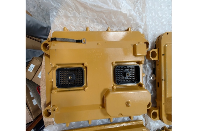
Engine Control Module (ECM)
The Engine Control Module (ECM), also often referred to as the Engine Control Unit (ECU) or Powertrain Control Module (PCM), is the electronic brain of a modern internal combustion engine. It is a type of embedded system that reads data from various sensors, processes this information, and then controls actuators to ensure optimal engine performance, fuel efficiency, and emissions control.
1. System Composition (Hardware & Software)
The ECM is a complex piece of hardware running sophisticated software. Its main components are housed within a rugged, weather-sealed case to protect it from the harsh engine environment.
A. Hardware Components:
Microprocessor (CPU - Central Processing Unit): The "brain" of the ECM. It executes the software instructions (the program) and performs all the calculations to make decisions.
Memory: The ECM uses several types of memory:
ROM (Read-Only Memory) / Flash Memory: Stores the program permanently, including the fuel and ignition maps, diagnostic routines, and other fixed data. This is the "firmware" or "calibration."
RAM (Random Access Memory): Temporarily stores calculated values, sensor data being processed, and diagnostic trouble codes. This data is lost when the ignition is turned off.
KAM (Keep-Alive Memory): A special type of RAM that retains information even when the ignition is off, powered directly by the car's battery. It stores adaptive learning values (like idle speed trim or fuel trim) that the ECM learns over time to compensate for engine wear.
Input/Output (I/O) Circuitry: This is the interface between the microprocessor and the outside world.
Input Conditioning Circuits: These clean up and convert the raw signals from sensors (e.g., crankshaft position sensor, oxygen sensor) into a digital format the microprocessor can understand. For example, they filter electrical noise and convert variable resistance into voltage.
Output Drivers: These are powerful electronic switches (often transistors) that turn on and off various actuators, such as fuel injectors, ignition coils, and relays for the cooling fan or fuel pump.
Power Supply: Manages the vehicle's electrical system voltage (which can fluctuate) and provides a stable, regulated voltage (e.g., 5V reference) for the sensors.
B. Software Components:
Main Control Program (Firmware): The core operating system and logic that dictates how the ECM operates.
Calibration Data (Maps): These are pre-programmed, three-dimensional lookup tables. For example, a fuel map will have engine speed (RPM) on one axis, engine load (MAP/MAF sensor) on another, and the resulting optimal injector pulse width (fuel amount) at the intersection. The ECM uses these maps to make split-second decisions.
2. Working Principle (The Control Loop)
The ECM operates in a continuous, high-speed loop. It repeats this process thousands of times per second.
INPUT: The ECM receives raw electrical signals from various sensors located throughout the engine. Examples include:
Crankshaft Position (CKP) Sensor: Engine speed (RPM) and position.
Mass Air Flow (MAF) or Manifold Absolute Pressure (MAP) Sensor: Engine load.
Coolant Temperature (ECT) Sensor: Engine temperature.
Throttle Position (TPS) Sensor: Driver demand.
Oxygen (O2) Sensor: Exhaust gas oxygen content.
PROCESSING: The microprocessor takes the conditioned input data. It compares the actual values to the desired values stored in its calibration maps. It performs complex calculations to determine the exact actions needed to achieve the target air-fuel ratio, spark timing, and idle speed. For example: "The engine is at 2000 RPM, under medium load, and is cold. According to my map, the injectors need to stay open for 4.5 milliseconds, and the spark plug needs to fire 10 degrees before top dead center."
OUTPUT: The ECM sends command signals through its output drivers to the various actuators to carry out the decisions. Examples include:
Turning the fuel injectors on and off for a precise duration.
Triggering the ignition coil(s) to fire a spark plug at the exact moment.
Opening or closing the Idle Air Control (IAC) valve to manage idle speed.
Modulating the signals to variable valve timing solenoids or turbocharger wastegates.
This entire process is a closed-loop control system. For critical functions like fueling, the ECM uses feedback from the oxygen sensor to fine-tune its output, ensuring the stoichiometric air-fuel ratio is maintained for optimal catalytic converter efficiency.
3. Main Functions
The ECM manages virtually every aspect of engine operation. Its primary functions include:
Fuel Management: Calculates and delivers the precise amount of fuel needed by controlling the fuel injectors' pulse width. This is based on inputs like RPM, load, and temperature.
Ignition Timing Control: Determines the optimal time to fire the spark plugs for maximum power and efficiency while preventing knock (detonation). It advances or retards the timing based on RPM, load, and signals from the knock sensor.
Idle Speed Control: Maintains a smooth and stable idle speed regardless of engine load changes (e.g., when the air conditioning compressor or power steering pump turns on) by controlling the IAC valve or electronic throttle body.
Emissions Control: Manages systems that reduce harmful emissions, such as the Exhaust Gas Recirculation (EGR) system, and monitors the efficiency of the catalytic converter and oxygen sensors.
Variable Valve Timing (VVT) Control: Adjusts the timing of the intake and/or exhaust valves to optimize performance, fuel economy, and emissions across the entire RPM range.
Turbocharger/Supercharger Control: In forced-induction engines, the ECM controls the wastegate or boost solenoid to regulate boost pressure and protect the engine from over-boosting.
Diagnostics (OBD - On-Board Diagnostics): Continuously monitors the sensors and actuators for electrical faults or performance issues. If a problem is detected, it stores a Diagnostic Trouble Code (DTC) in its memory and illuminates the Malfunction Indicator Lamp (MIL), commonly known as the "Check Engine" light.
4. Maintenance and Diagnosis
The ECM itself is a very reliable solid-state device and rarely fails. Problems are almost always related to its inputs (sensors) or outputs (actuators/wiring).
Maintenance:
There is no routine maintenance for the ECM itself, but you can maintain the system it controls:
Keep the Battery Healthy: A failing battery or poor electrical connections can cause voltage spikes or drops, which can stress the ECM's delicate electronics or lead to erratic behavior.
Ensure Good Grounds: All engine and chassis grounds must be clean and tight. A poor ground is a common cause of weird, hard-to-diagnose sensor readings.
Keep Connectors Clean and Sealed: Ensure the main ECM connector and all sensor connectors are free from corrosion, moisture, and damage. Never "probe" a connector from the front, as this can damage the seal and cause future corrosion.
Diagnosis:
Diagnosing an ECM-related issue follows a logical, step-by-step process. Never replace an ECM without first checking everything else.
Retrieve Diagnostic Trouble Codes (DTCs): An OBD-II scanner is the first tool. The code (e.g., P0302 for cylinder 2 misfire) provides a starting point, but it tells you what system has a problem, not necessarily which part is bad.
Verify the Code with Visual Inspection & Data: Check for obvious issues like vacuum leaks, damaged wires, or corroded connectors. Use the scanner's "live data" function to view sensor readings. For a misfire code, you might look at coolant temperature, fuel trims, and oxygen sensor readings to gather clues.
Check the "Easy" Things First: Before suspecting the ECM, test the sensors and actuators that are related to the DTC. For example, if you have a crankshaft position sensor code, test that sensor and its wiring according to the service manual.
Check Power and Grounds to the ECM: A common cause of an apparently "dead" ECM is a blown fuse or a corroded ground wire. The ECM needs power and a good ground to function.
Perform Component and Circuit Tests: Using a multimeter, you can test the resistance of sensors, check for continuity in wiring, and verify that voltage signals are reaching the ECM.
Seek Professional Diagnosis: If all inputs, outputs, power supplies, and grounds check out, and the problem persists, the ECM may be faulty. This is rare. ECM failure often requires reprogramming (flashing) by a dealership or a specialized shop, as the new module must be programmed with the correct software for that specific vehicle.